Field Sites
Hidden
Field 1
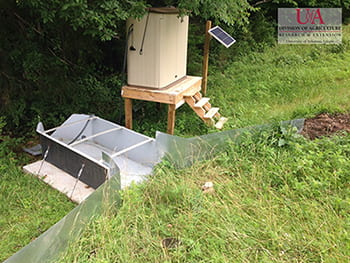
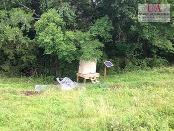
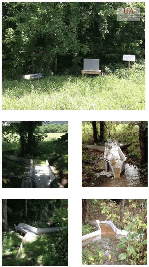
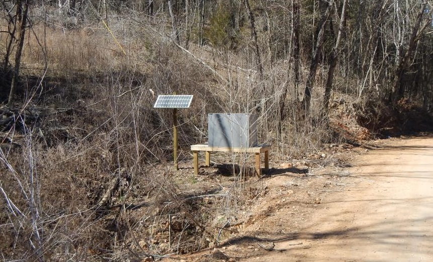
On Field 1, BCRET is monitoring surface runoff, which is measured at the flume pictured below. Samples are automatically collected for chemical analysis when runoff occurs.
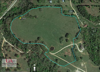
A map of Field 1 shows the area that is measured for surface runoff and where the flume is located.
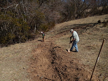
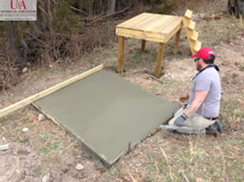
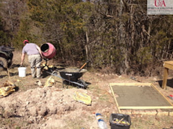
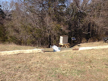
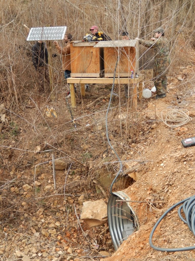
The photos below show the flume construction process on Field 1. Piezometers were not installed on this field due to the shallow nature of the overlying soils.
Field 5a
We have installed soil water recorders and piezometers to constantly measure water table depth at several points in the field, shown on the map below and take samples for chemical analysis. 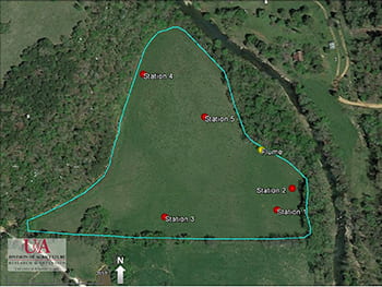
This Field is not currently permitted to receive manure but we will continue to monitor runoff and leaching to determine background losses as a result of prior management of these fields.
Field 12
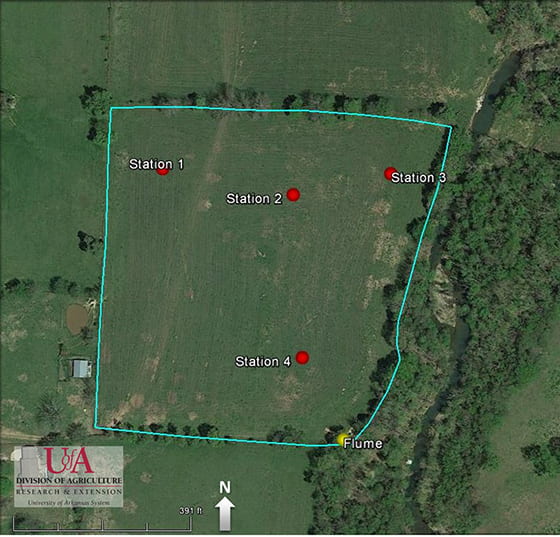
On Field 12, BCRET is monitoring surface runoff and the movement of water down through the soils. Surface runoff is measured at the flume pictured and samples are automatically collected for chemical analysis when runoff occurs. ![]()
We have installed soil water recorders and piezometers to constantly measure water table depth at several points in the field, shown on the map and take samples for chemical analysis.
Spring
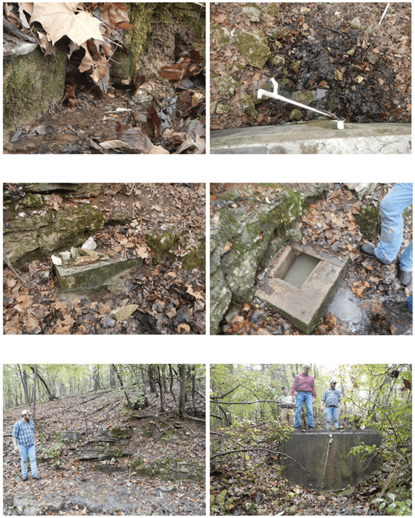
BCRET manually collects water samples from a spring which drains below draining Field 1, which is permitted to receive swine slurry. The samples are analyzed for nutrients, sediment and bacteria.
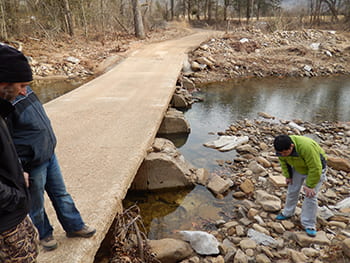
Culvert
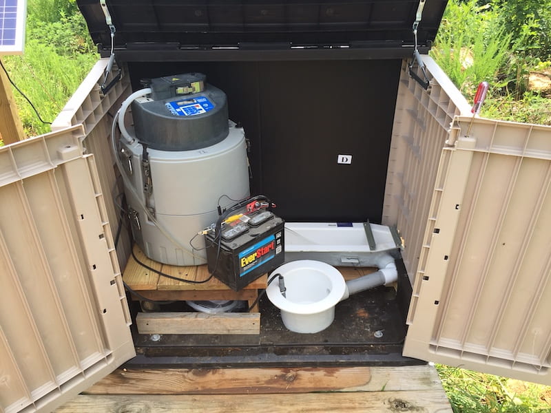
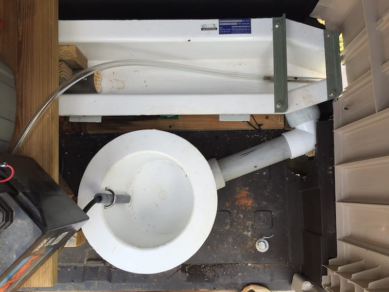
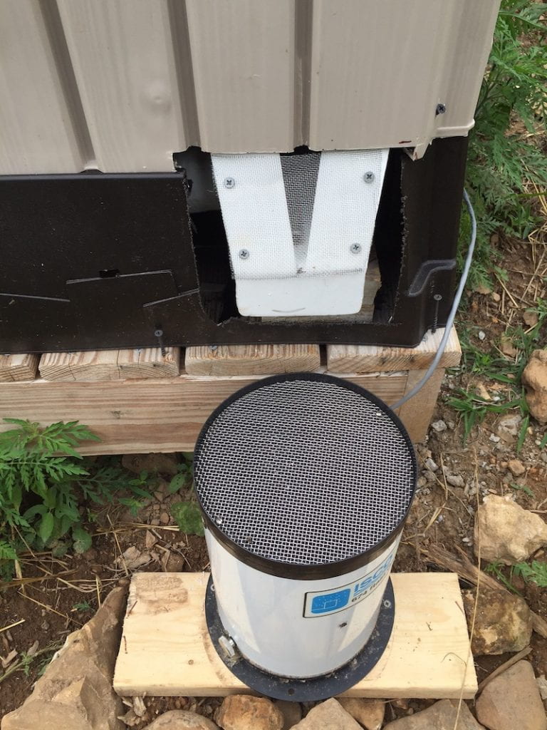
At the Ephemeral Stream site (BC4), BCRET is monitoring stream flow and quality by a velocity flow meter in a culvert opening directing water under an unpaved road (County Road 41)and by an ISCO sampler, respectively.
Downstream of Farm
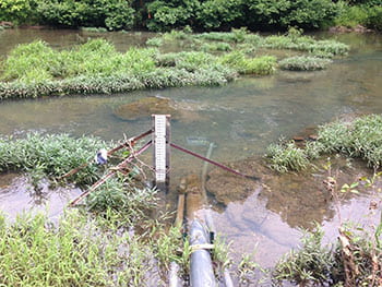
At the downstream site we contracted with USGS, who installed flow gauging equipment to continuously monitor the flow of Big Creek, as it leaves the drainage area encompassing the fields permitted to receive swine slurry. At this site we have automatic water samplers that will start collecting water during storm events for subsequent chemical analysis and USGS have deployed a nitrate sensor. The information obtained by USGS at this site is provided real-time on their dedicated website. We also have an in-stream sensor that will continuously measure water temperature, dissolved oxygen, turbidity, pH, and electrical conductivity.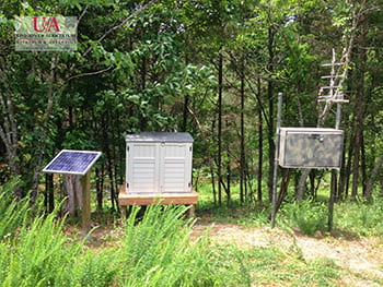
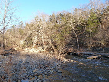
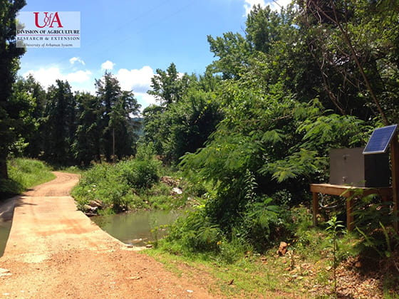
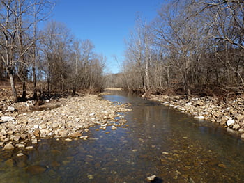
Upstream of Farm
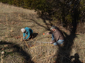
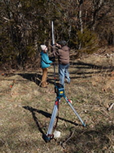
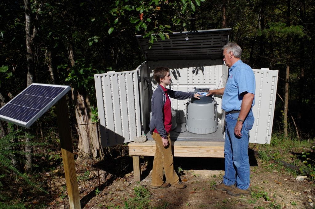
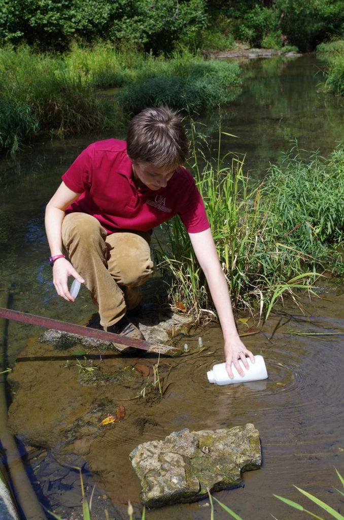
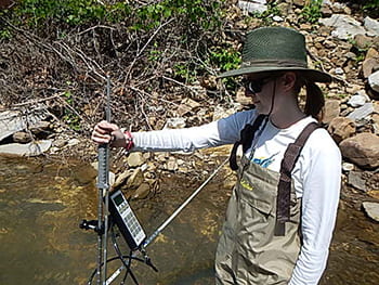
At the upstream site, BCRET has installed flow gauging equipment to continuously monitor the flow of Big Creek as it enters the drainage area encompassing the fields permitted to receive swine slurry. At this site we have an automatic water sampler that will start collecting water during storm events for subsequent chemical analysis. We also have an in-stream sensor that will continuously measure water temperature, dissolved oxygen, turbidity, pH, and electrical conductivity.
Larry Berry (top) and Pearl Webb (bottom) using monitoring equipment to measure the contents of the water upstream of the farm.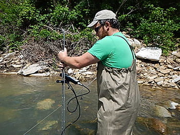
Left Fork
At the Left Fork site BCRET has installed flow gauging equipment to continuously monitor the flow of Big Creek as it enters the drainage area encompassing the fields permitted to receive swine slurry. At this site we have an automatic water sampler that will start collecting water during storm events for subsequent chemical analysis.
Left Fork, looking upstream,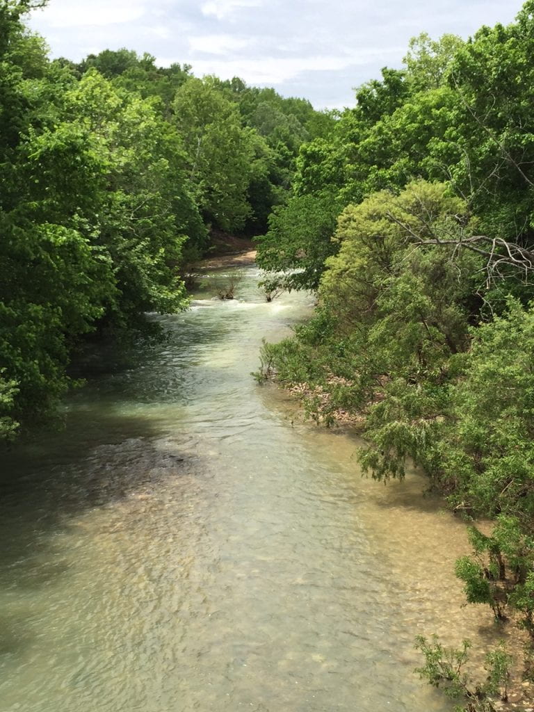
Left Fork, looking downstream,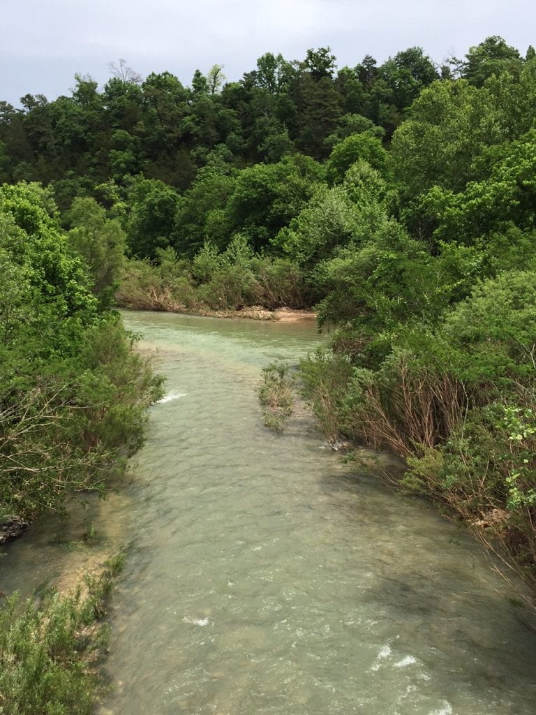
USGS equipment on as seen from road level,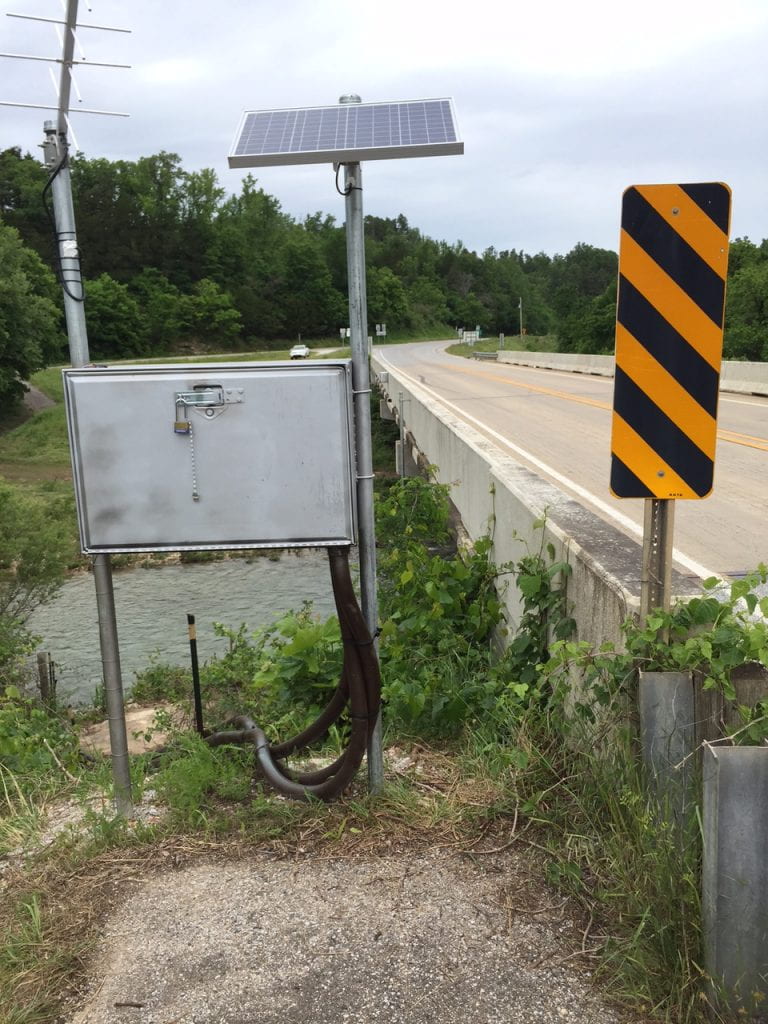
USGS equipment, bank view,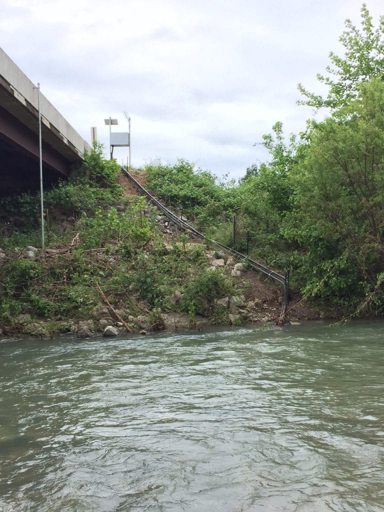
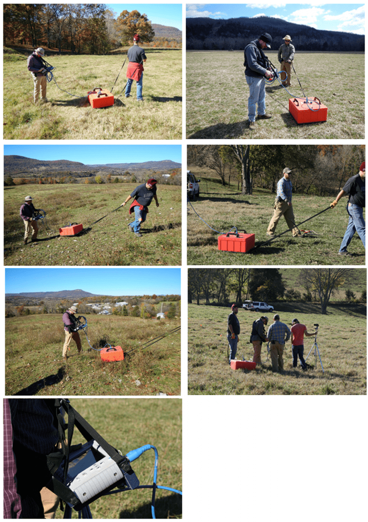
Ground Penetrating Radar
NRCS conducted a survey of the material underlying Fields 1, 5a, and 12 using ground penetrating radar (GPR). Members of BCRET are shown using the equipment used in this survey in the following pictures.
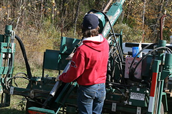
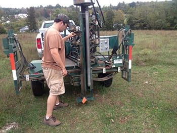
Grid Soil Sampling
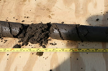
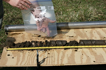
BCRET collected soil samples from the fields permitted to receive swine slurry on a much more detailed frequency than normal to determine the distribution patterns of nutrients in theses soils, at the surface and with depth.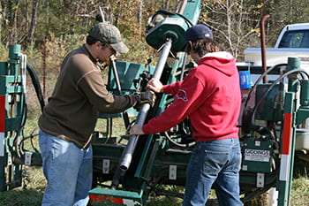
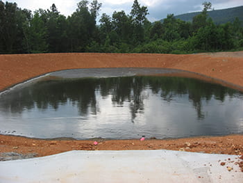
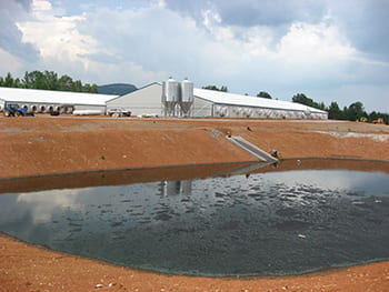
Slurry Holding Pond
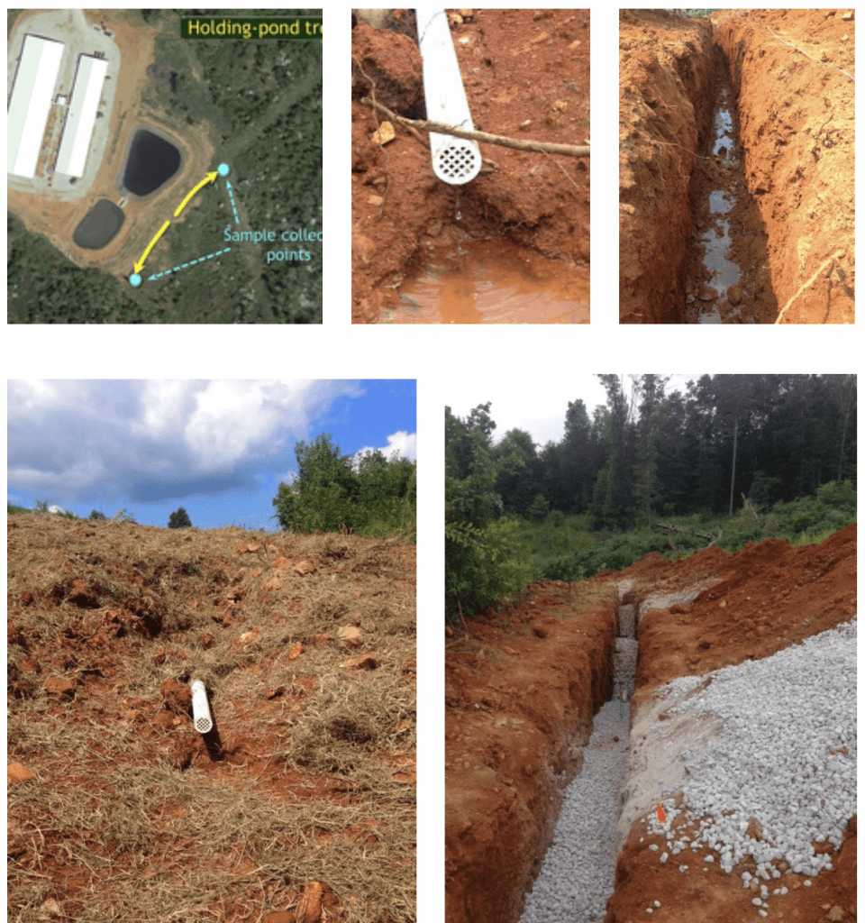
We are periodically collecting samples of manure slurry in the holding ponds for chemical analysis. At the site we also collected water from a well adjacent to the ponds for chemical analysis. We have also installed a trench downslope of the holding ponds that will intercept liquids seeping out of the bottom of the ponds. The trenches have a pipe out-letting at the surface, where we collect samples for analysis.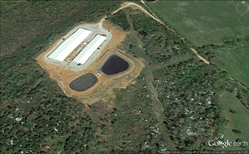
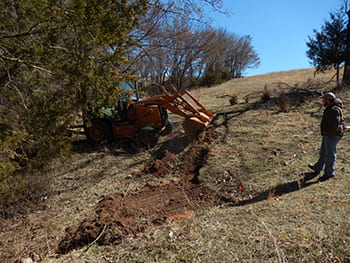
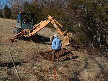
Interceptor Trench
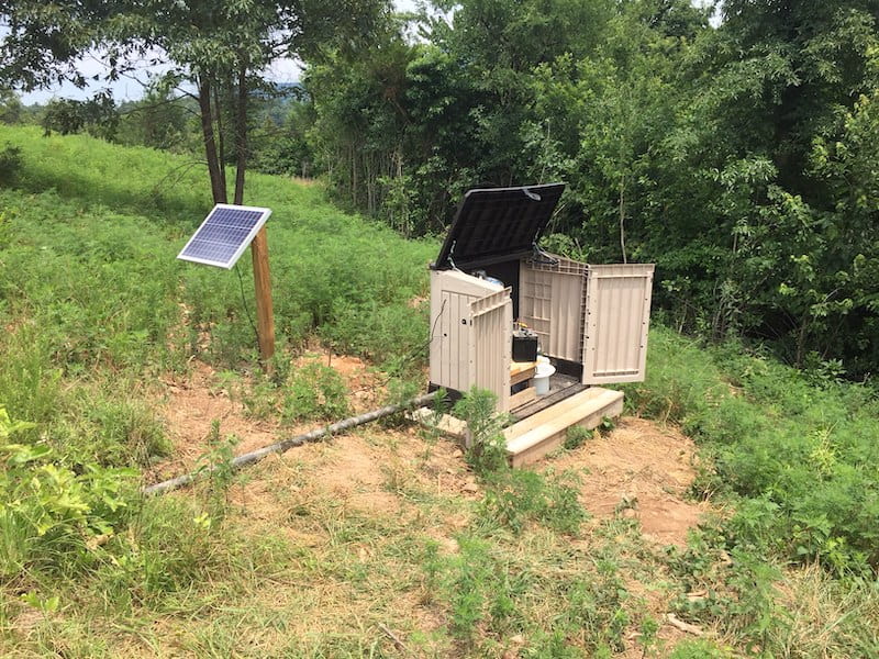
The base of the interceptor trench was lined with impermeable plastic sheeting to capture all flow moving through trench walls into the trench. A 4-inch perforated pipe was laid on top of the plastic sheet and the trench filled with washed gravel to a depth of 2-3 feet below the soil surface. The remaining trench was then backfilled with compacted soil and seed and hay placed on the surface to encourage surface vegetation regrowth. The design will capture any flow moving horizontally into the trench, and direct flow for collection and transmittal to the outlets where flow rate can be measured and samples is collected for water-quality analyses. Water exiting the interceptor trench pipe outlets was sampled by hand prior to instrumenting both pipes with flow monitoring, sonde, and ISCO sampler to continuously measure flow and automatically collect water samples.
Piezometers
Water-level sensors (Water Logger WL-15 units from Global Water) were installed by BCRET on Fields 5a and 12 to continuously monitor the water table depth along two transects in Field 12 and in several strategic locations in Field 5a. The soil water-level sensors determine the depth at which soil is saturated with water (or the water-table depth) at four-hour intervals down to average depths of 6 to 7 feet, with the deepest being 9.7 feet below the surface, which is the depth where soil was underlain by a cherty or discontinuous layer (i.e., point of refusal).
At each site, two piezometers were also installed that allow collection of an in-situ soil water sample. The piezometers consist of 5-cm (2-inch) diameter Schedule 40 PVC pipe, which were slotted in the bottom 10 cm of the pipe to facilitate water flow. Sand was placed in the bottom of the hole and along the outside of the PVC pipe up to the top level of the slots in the pipe. Bentonite chips were placed above the sand along the outside of the PVC pipe to the soil surface to ensure no preferential movement of water along the well casing. Piezometers were installed so that there was no piping or equipment above ground that could interfere with day to day farm operations on the field.
Data is downloaded from each unit using a laptop computer approximately once a month. One piezometer was located to collect water from just below the root zone (about 12 inches deep) and one from the deeper point of refusal, described above.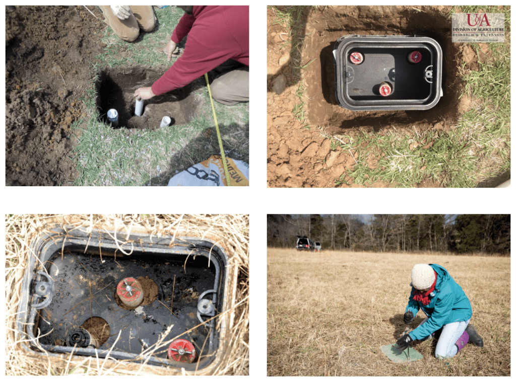
Electrical Resistivity Imaging
Electrical resistivity imaging (ERI) provides a good method to understand the distribution of fluids and rock properties in the subsurface environment especially in the presence of fractures or karst features. The method allows an electrical image to be created with a resolution of half the distance between electrodes, which typically provides a meter-scale dataset that can be utilized to evaluate heterogeneity and fluid distribution. Improvements in sensitivity generated by the Halihan/Fenstemaker method allow greater differentiation of these signatures. In a field setting, this will result in a two-dimensional mapping of subsurface electrical properties for each dataset, which will be used to interpret groundwater movement in a complex mantled karst with applied manures.As part of cooperative research, Oklahoma State University (OSU) designed and conducted ERI imaging experiments and will integrate ERI data with well and other site data to provide an understanding of the subsurface distribution of flowpaths at a background and manure study site. Dr. Todd Halihan and his graduate research assistant (OSU) travelled to the sites to conduct the imaging and data collection.
The work was conducted in late December, 2014 and data quality is anticipated to be high due to the geologic setting lacking metallic infrastructure. The resistivity structure of the site will be evaluated with OSU working with UA and Aestus to ensure proper integration of the ERI acquisition location and scale with the UA well and soil sampling protocols. Data acquired during the ERI analysis of Fields 5a and 12 will be processed and analyzed by OSU researchers during the first quarter of 2015 and results will be made available in the next Quarterly Report, due April 15, 2015.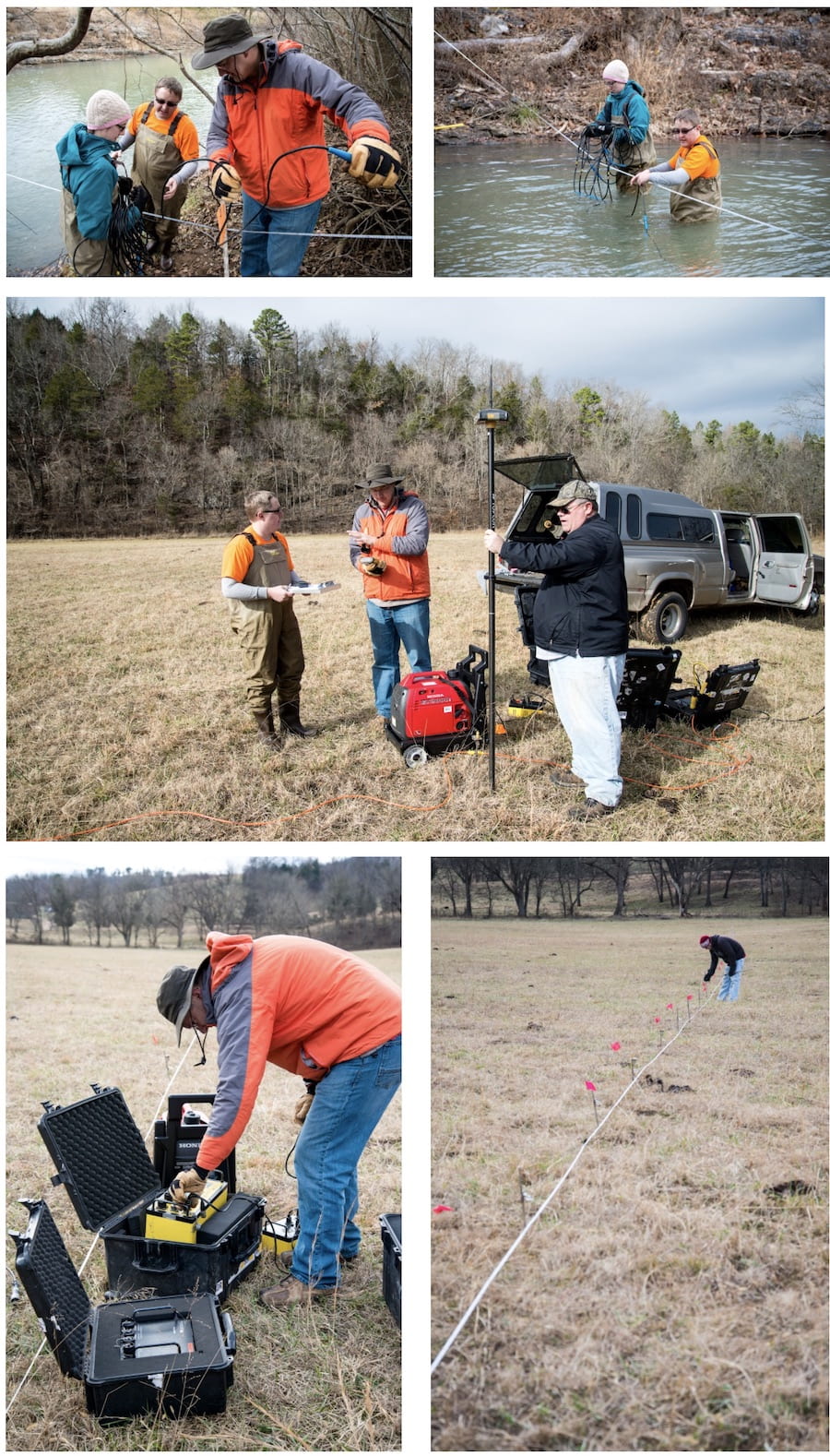
Project Contact
Andrew Sharpley, Ph.D.
Distinguished Professor of Soils and Water Quality
Phone: 479-575-5721
Fax: 479-575-7465
Email: sharpley@uark.edu
115 Plant Science Building
University of Arkansas
Fayetteville, AR 72701